
Cylinder # in the Usual Sparkplug Firing Order ( To Show Where the Cylinders are Relative to one Another in terms of What Stroke They Are In ):
13 42
PowerCompressionIntakeExhaust
ExhaustPowerCompIntake
IntakeExhaustPowerComp
CompIntake Exhaust Power
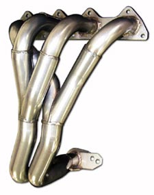
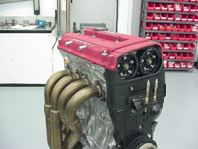
Headers "join" or "merge" exhaust pulses together after they come out of each cylinder. Each pulse has "energy". Energy or "flow momentum" that is used to suck the exhaust gas out of the cylinder. The more energy the pulse has, the faster the pulse travels. The faster the pulse travels, the lower pressure you get in the tube downstream away from the engine: less backpressure (or more suck out of the engine) . We want fast flowing exhaust pulse(s) leaving the engine.
We've superficially talked about sequential (1-2, 3-4) vs. nonsequential (1-4, 2-3)header primaries pairing on TI.net before. By sequential we mean that one exhaust pulse immediately follows another rather than having a gap of 1 extra stroke in between each pulse. Let's delve into it a little futher in detail.
Look at the table above where the exhaust strokes are relative to each other when we fire our Integras in the usual 1-3-4-2 firing order.When you pair or join 2 exhaust pulses from cylinders 1-2 rather thancylinders 1-4, they are 180 crank degrees apart from one another and not 360 degrees apart (180 degrees is from TDC to BDC or from BDC to TDC). They 2 sequential pulses are closer together in time as they travel out of the engine compared to the 2 nonsequential pulses.
In simple terms, the 2 sequentially merged exhaust pulses are 1 stroke difference away from one another compared to the 2 nonsequential pulses which are 2 strokes apart from another.
The energy or momentum of the 2 paired pulses leaving the enginein your header is "higher" (compared to a single exhaust pulse or wave coming out of 1 cylinder) ,with a big reflected wave kicking back towards the engine afterwards as well.
If 2 pulses are closer together, they will carry more energy when they are merged compared to 2 pulses that are set further apart (i.e.the "energy" dissipates the further they travel down the tubing). The energy is focused at a specific rpm range (upper powerband). In a nonsequential pairing because the pulses are further apart, the overall energy is less and is more spread out in time and the powerband is a bit broader but the power comes on at a lower rpm.
So you get a bigger "kick" out of the exhaust pulses at higher rpms after the merge point when the 2 pulses are closer together in time compared to when cylinders 1 & 4 are being joined or paired together by the header.
more "kick" or more exhaust flow "energy" or more exhaust flow "momentum" by the pulse means that it causes more suction or pull out of the cylinder to yank out any exhaust gas left behind in the cylinder that wasn't "pumped out" by the piston on the exhaust stroke itself ("blow down period").
Now there is also a reflected wave that goes back towards the engine. The dreaded "backpressure" effect that semi-counters this forward flow "kick" after 2 pulses are merged.
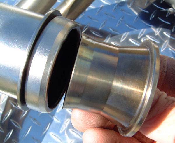
That's why having a stepped header helps. It prevents the reflected wave from going back to the engine or cylinder. The step in diameter prevents the reflected wave from getting there using a "dam" to block it (also called a "reversion dam"). Don't ask about the reversion chambers in the primaries because I have no clue how those work.
Now, I have to figure out what happens if we cross the cylinder 1-2 paired pulses into the secondary that would normally be meant for cylinders 3-4 pairing. I'm not sure if that helps (i.e. adds any energy).
PS Thanks goes to Dave Stadulis for taking the time and explaining to me the complex idea of cylinder firing order and the strokes relative to one another between cylinders.
That table neatly summarizes and allows you to visualize this concept all in one shot.
13 42
PowerCompressionIntakeExhaust
ExhaustPowerCompIntake
IntakeExhaustPowerComp
CompIntake Exhaust Power
Headers "join" or "merge" exhaust pulses together after they come out of each cylinder. Each pulse has "energy". Energy or "flow momentum" that is used to suck the exhaust gas out of the cylinder. The more energy the pulse has, the faster the pulse travels. The faster the pulse travels, the lower pressure you get in the tube downstream away from the engine: less backpressure (or more suck out of the engine) . We want fast flowing exhaust pulse(s) leaving the engine.
We've superficially talked about sequential (1-2, 3-4) vs. nonsequential (1-4, 2-3)header primaries pairing on TI.net before. By sequential we mean that one exhaust pulse immediately follows another rather than having a gap of 1 extra stroke in between each pulse. Let's delve into it a little futher in detail.
Look at the table above where the exhaust strokes are relative to each other when we fire our Integras in the usual 1-3-4-2 firing order.When you pair or join 2 exhaust pulses from cylinders 1-2 rather thancylinders 1-4, they are 180 crank degrees apart from one another and not 360 degrees apart (180 degrees is from TDC to BDC or from BDC to TDC). They 2 sequential pulses are closer together in time as they travel out of the engine compared to the 2 nonsequential pulses.
In simple terms, the 2 sequentially merged exhaust pulses are 1 stroke difference away from one another compared to the 2 nonsequential pulses which are 2 strokes apart from another.
The energy or momentum of the 2 paired pulses leaving the enginein your header is "higher" (compared to a single exhaust pulse or wave coming out of 1 cylinder) ,with a big reflected wave kicking back towards the engine afterwards as well.
If 2 pulses are closer together, they will carry more energy when they are merged compared to 2 pulses that are set further apart (i.e.the "energy" dissipates the further they travel down the tubing). The energy is focused at a specific rpm range (upper powerband). In a nonsequential pairing because the pulses are further apart, the overall energy is less and is more spread out in time and the powerband is a bit broader but the power comes on at a lower rpm.
So you get a bigger "kick" out of the exhaust pulses at higher rpms after the merge point when the 2 pulses are closer together in time compared to when cylinders 1 & 4 are being joined or paired together by the header.
more "kick" or more exhaust flow "energy" or more exhaust flow "momentum" by the pulse means that it causes more suction or pull out of the cylinder to yank out any exhaust gas left behind in the cylinder that wasn't "pumped out" by the piston on the exhaust stroke itself ("blow down period").
Now there is also a reflected wave that goes back towards the engine. The dreaded "backpressure" effect that semi-counters this forward flow "kick" after 2 pulses are merged.
That's why having a stepped header helps. It prevents the reflected wave from going back to the engine or cylinder. The step in diameter prevents the reflected wave from getting there using a "dam" to block it (also called a "reversion dam"). Don't ask about the reversion chambers in the primaries because I have no clue how those work.
Now, I have to figure out what happens if we cross the cylinder 1-2 paired pulses into the secondary that would normally be meant for cylinders 3-4 pairing. I'm not sure if that helps (i.e. adds any energy).
PS Thanks goes to Dave Stadulis for taking the time and explaining to me the complex idea of cylinder firing order and the strokes relative to one another between cylinders.
That table neatly summarizes and allows you to visualize this concept all in one shot.